Complex Mechanical Assemblies
BiboFill is a complete mechanical assembly documented in SolidWorks 2025. My work connects the machine layout to its welded frame, liquid and backpressure circuits, HMI enclosure and purchased components, then translates the design into fabrication drawings, sheet-metal DXFs, STEP geometry and structured BOM information.
Scope
- Complete-machine and subassembly CAD documentation
- Welded structures, tube details, formed sheet-metal parts and component interfaces
- Thickness-grouped laser-cutting DXFs and STEP manufacturing handoff
- Excel BOM, drawing parts lists and revision-based production documentation
BiboFill — Complete Mechanical Assembly
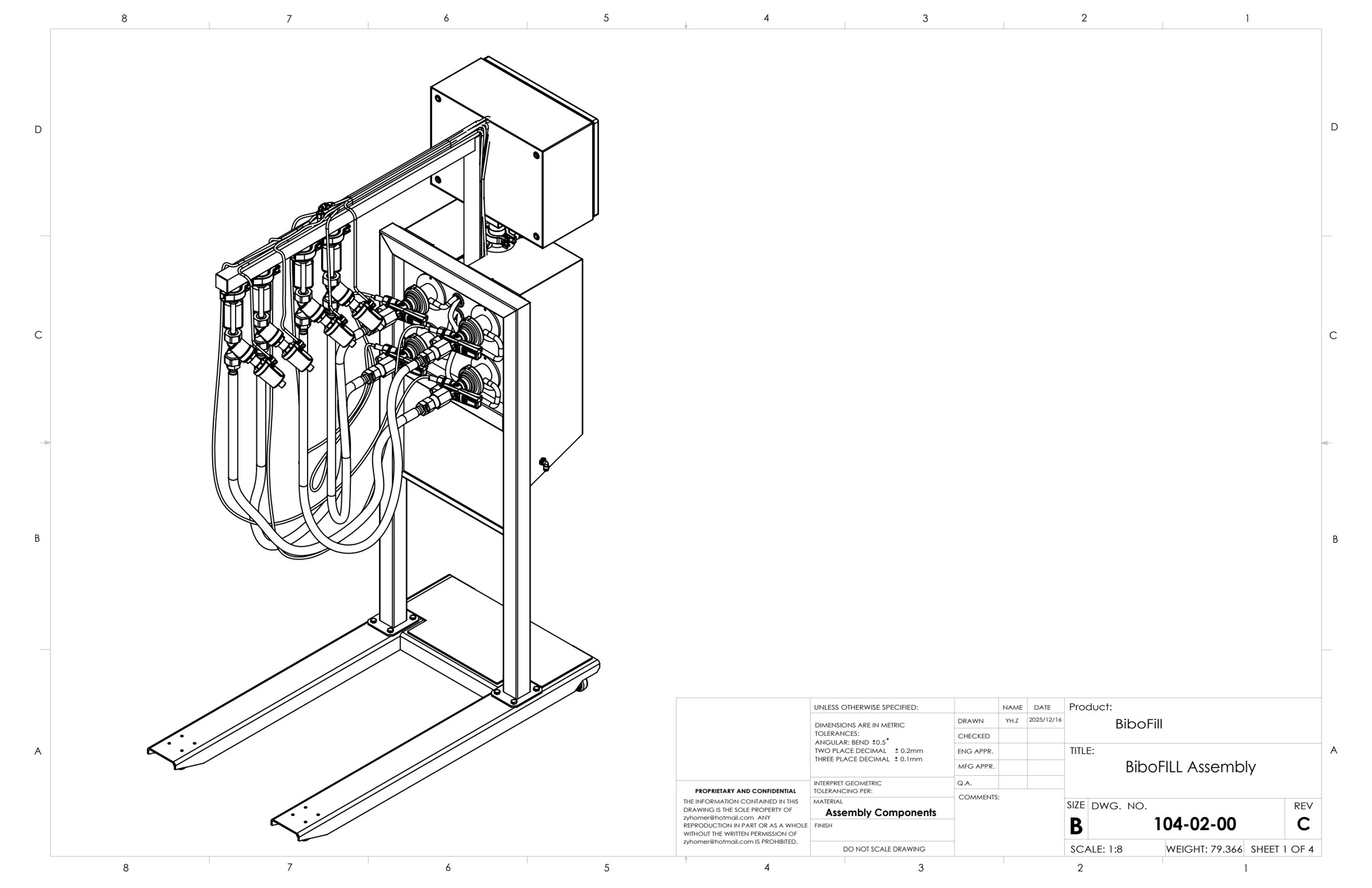
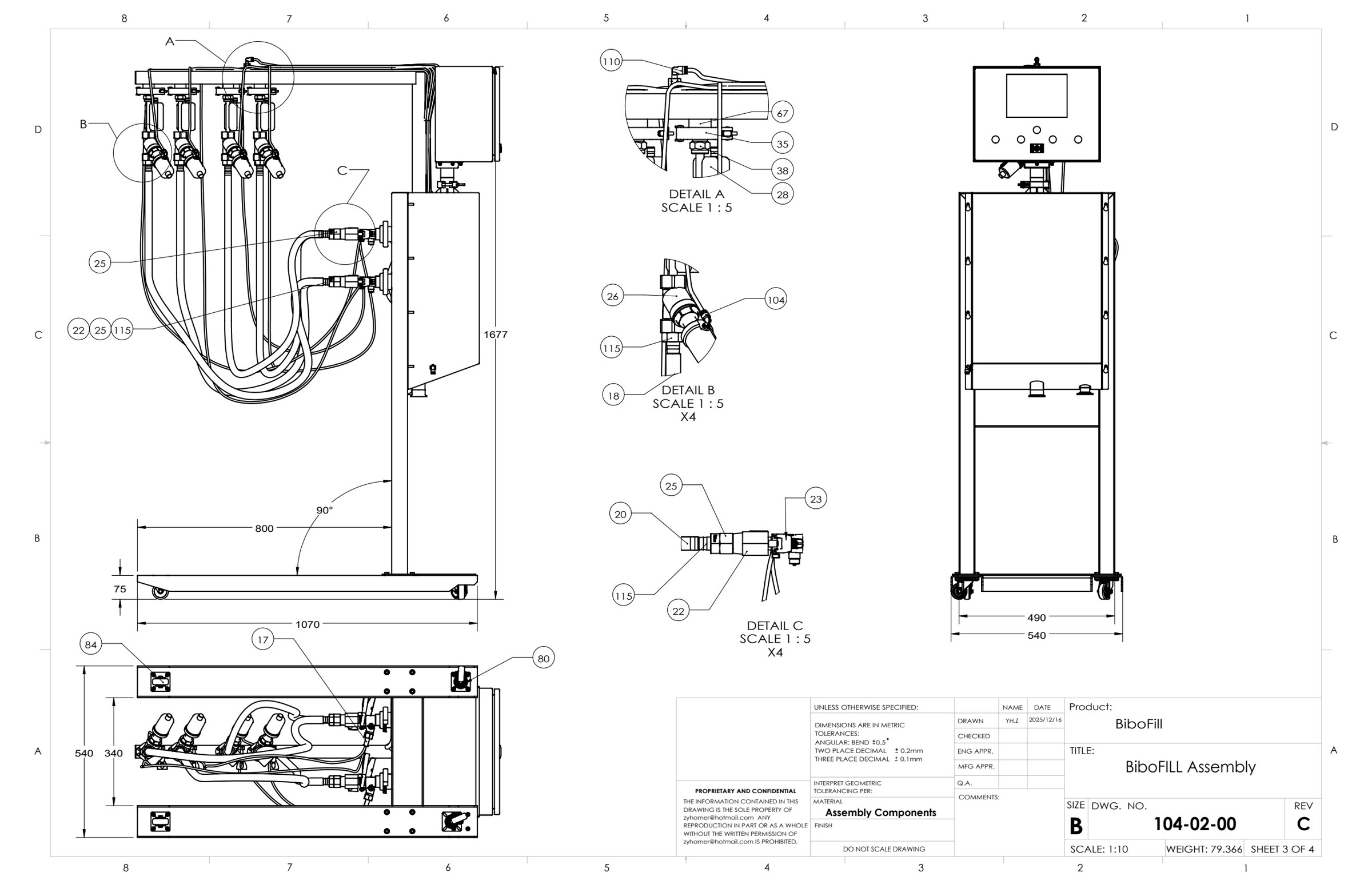
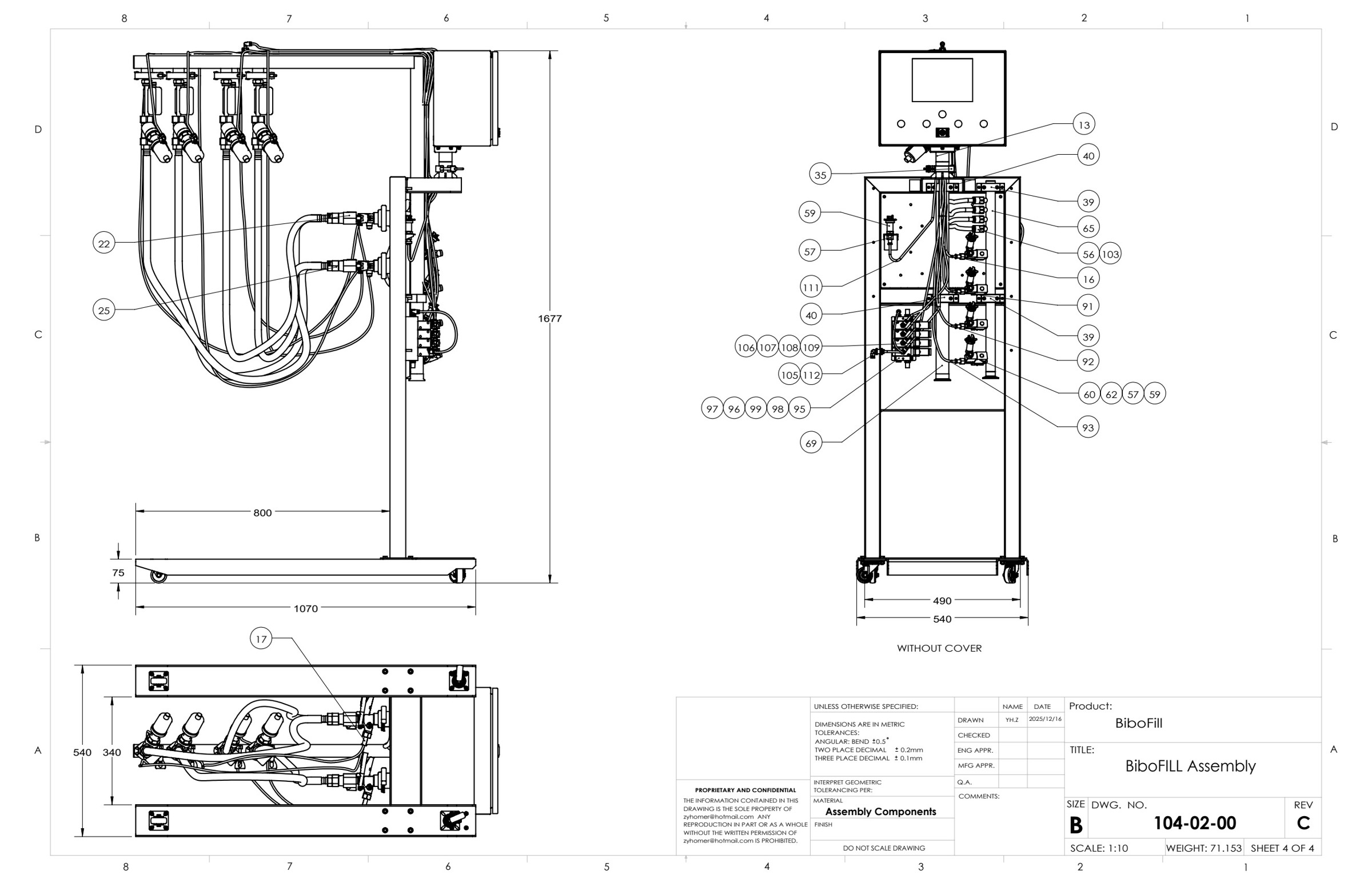
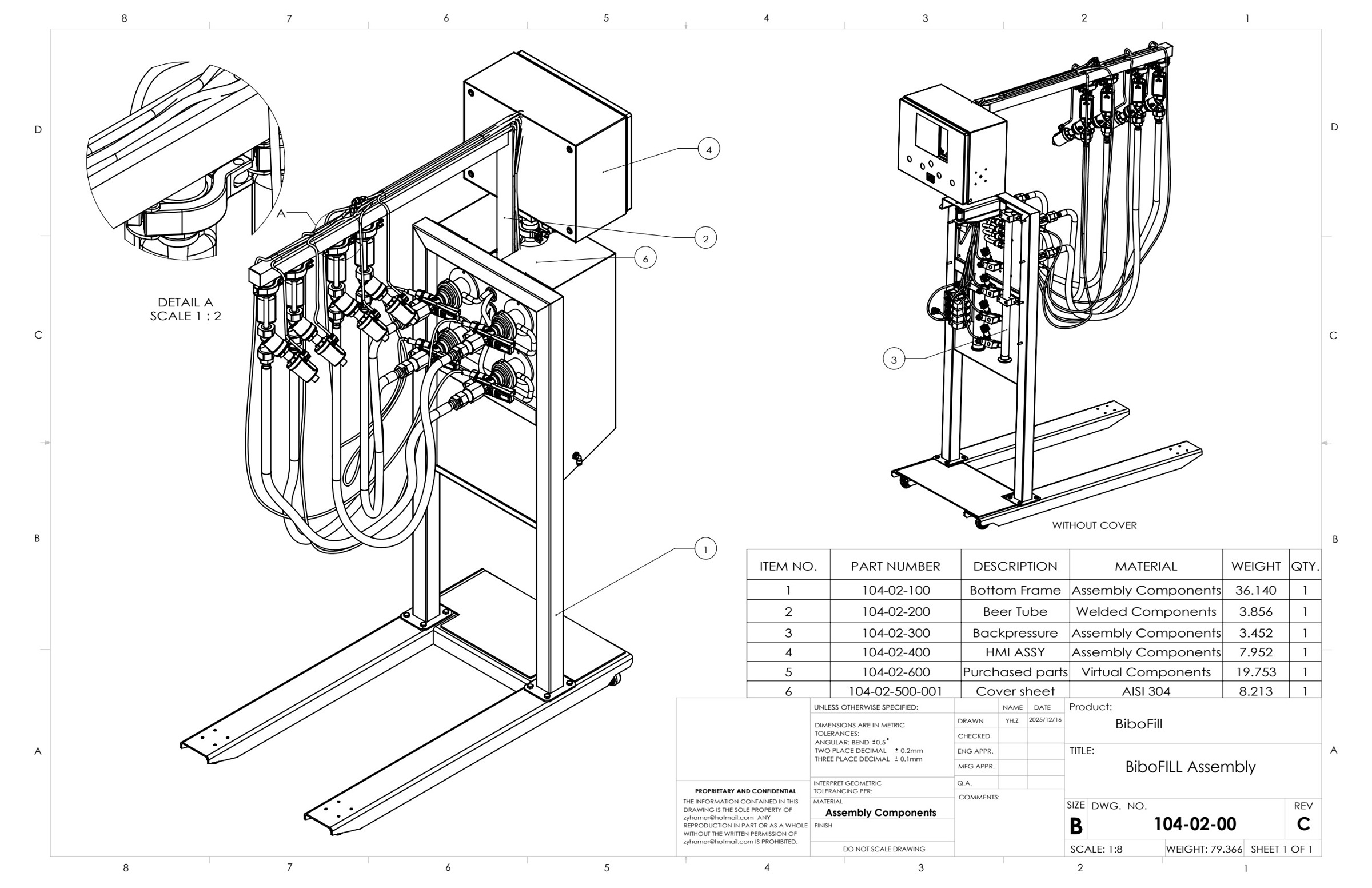
A multi-module filling-equipment assembly connecting a fabricated frame, liquid circuit, backpressure system, HMI enclosure, cover and purchased components. The Rev C documentation shows the complete machine, its installation envelope and the internal arrangement with the cover removed.
- Whole-machine assembly and dimensioned general arrangement
- Covered and uncovered views for component access and interface review
- Module identification linking the overall assembly to subassemblies and parts
Select any image to view the full-size drawing or photograph.
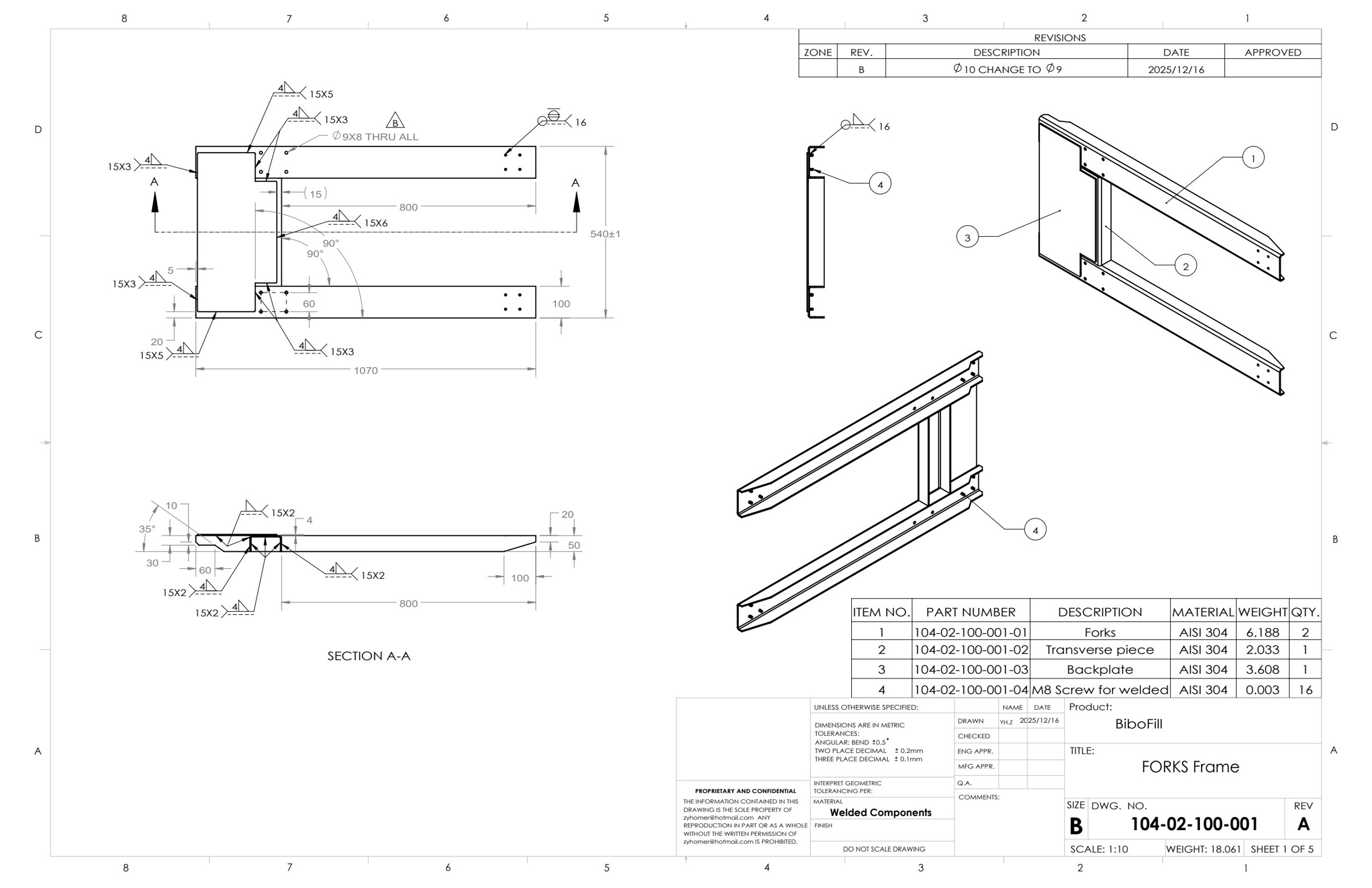
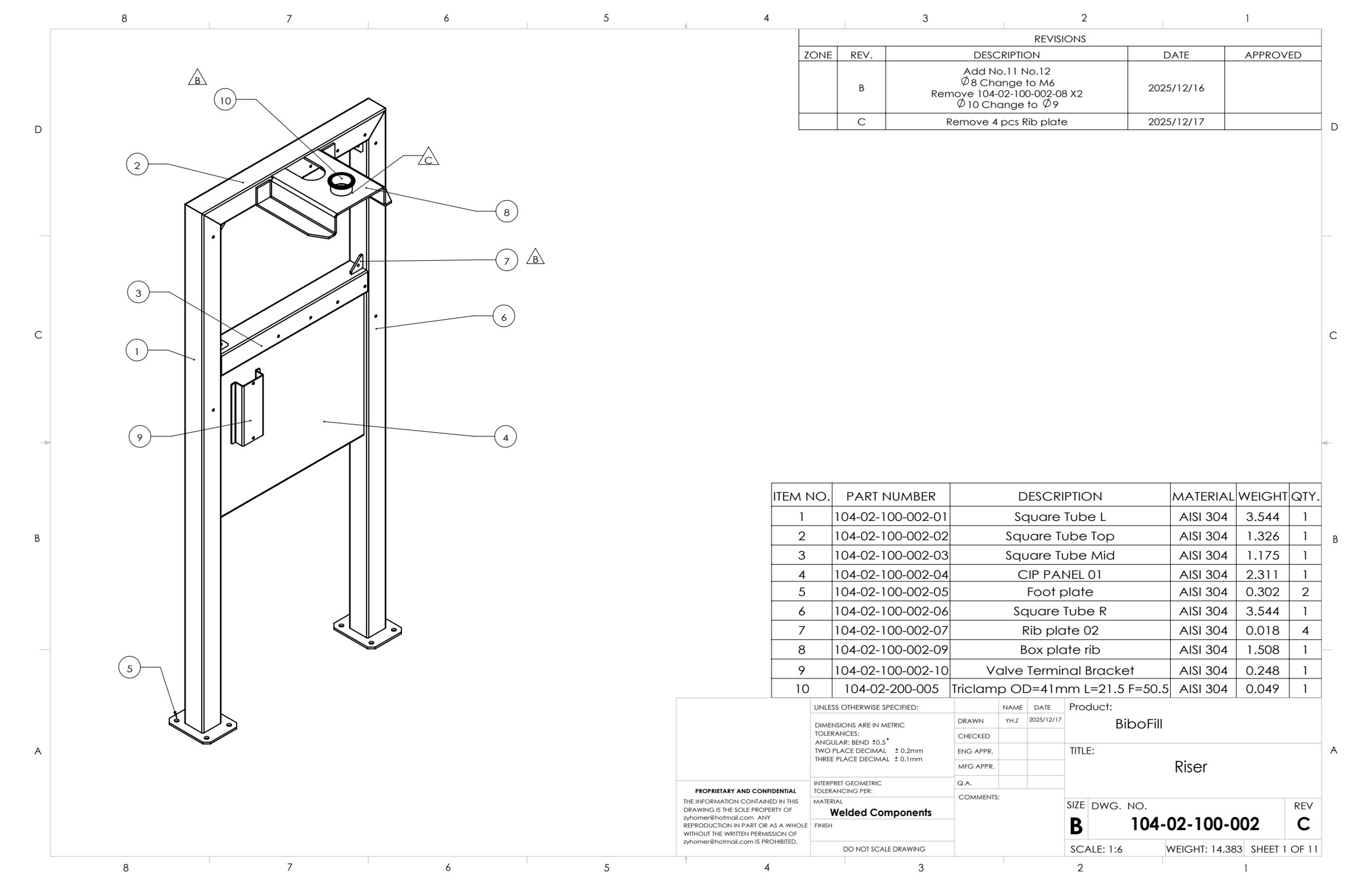
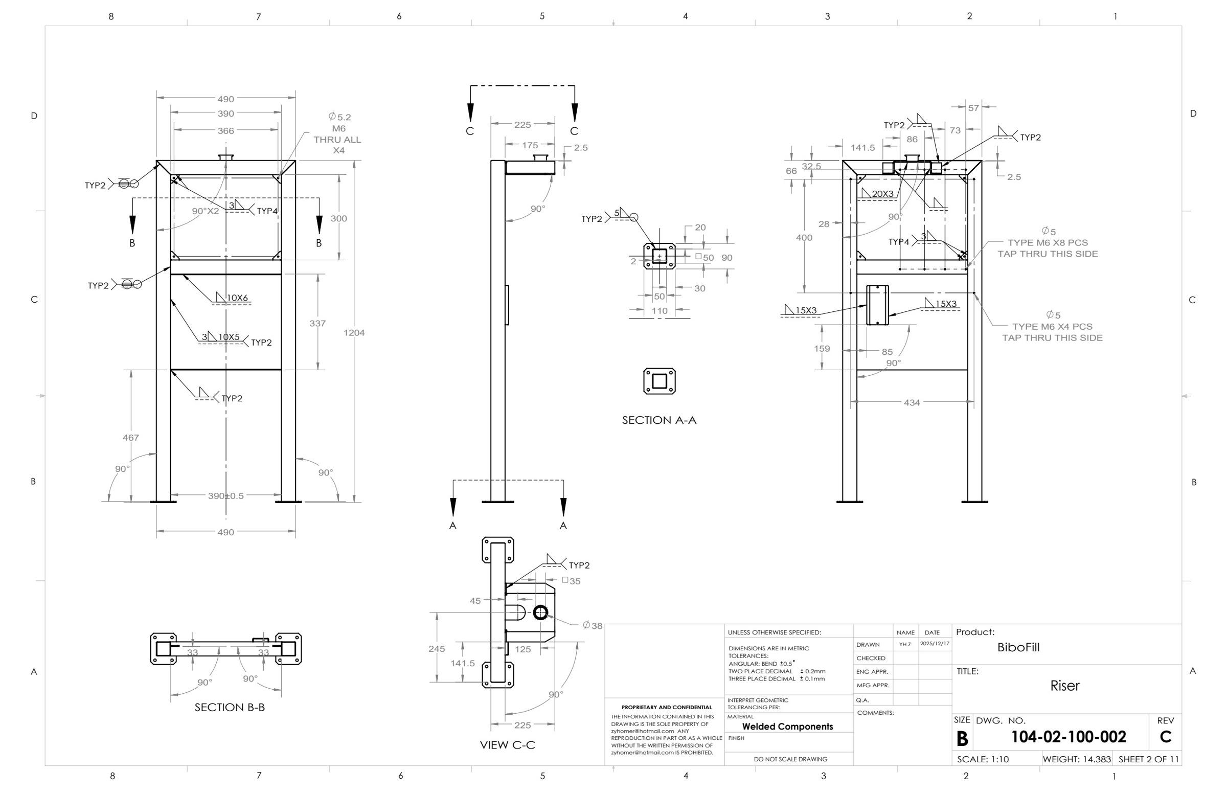
Bottom Frame, Forks & Riser
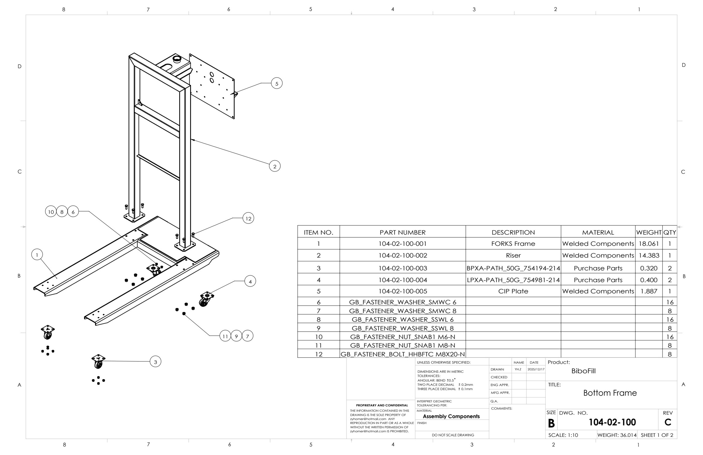
The supporting structure is documented as a bottom-frame assembly with separate fork-frame and riser weldments. Detail sheets connect the assembled structure to tube members, formed plates, fasteners and local weld requirements.
- Bottom-frame assembly with component balloons and quantities
- Fork-frame fabrication with sections, plate interfaces and weld callouts
- Riser weldment with dimensions, sections, mounting locations and revision records
Select any image to view the full-size drawing or photograph.
Liquid Circuit & Backpressure Components
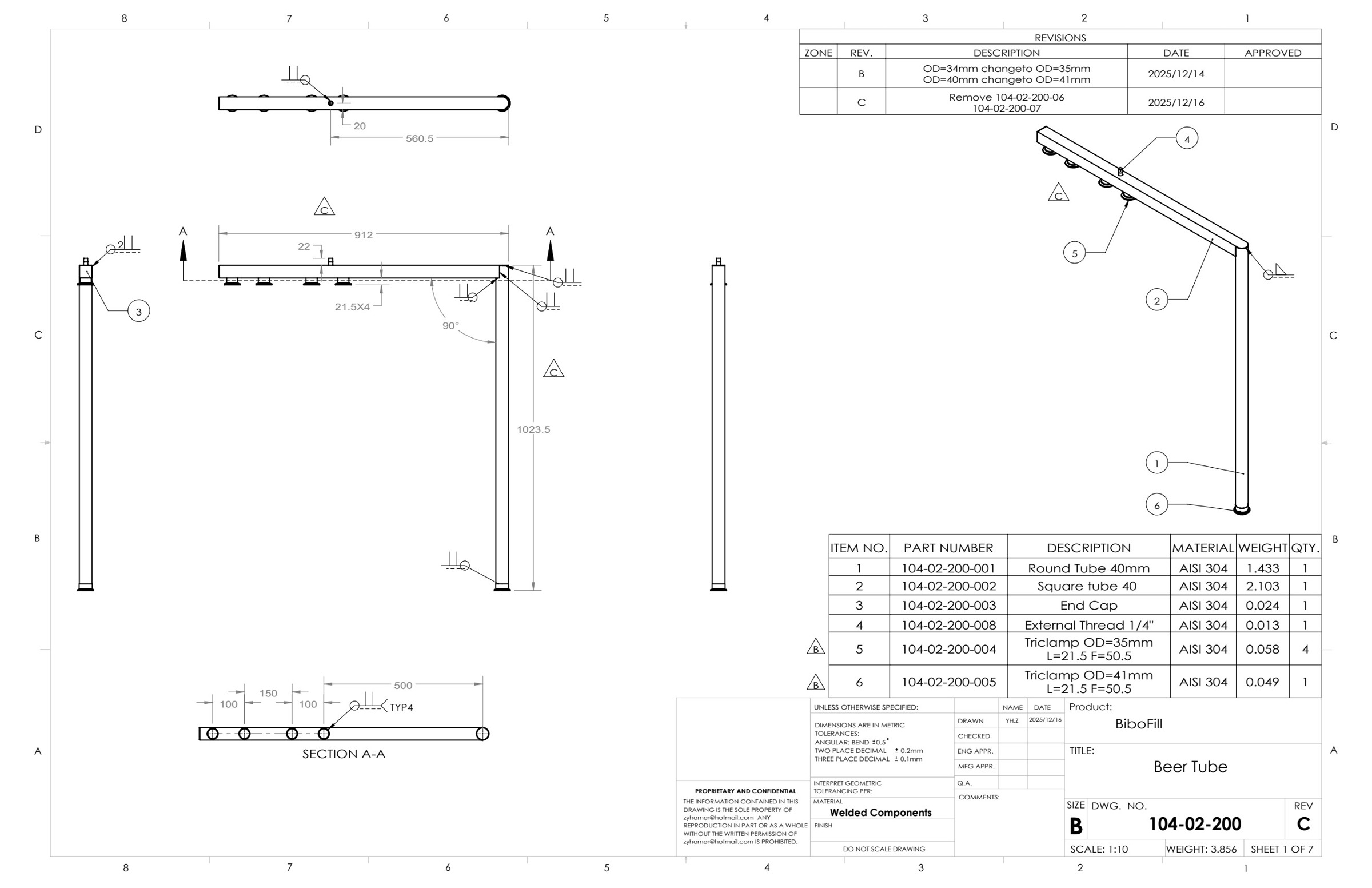
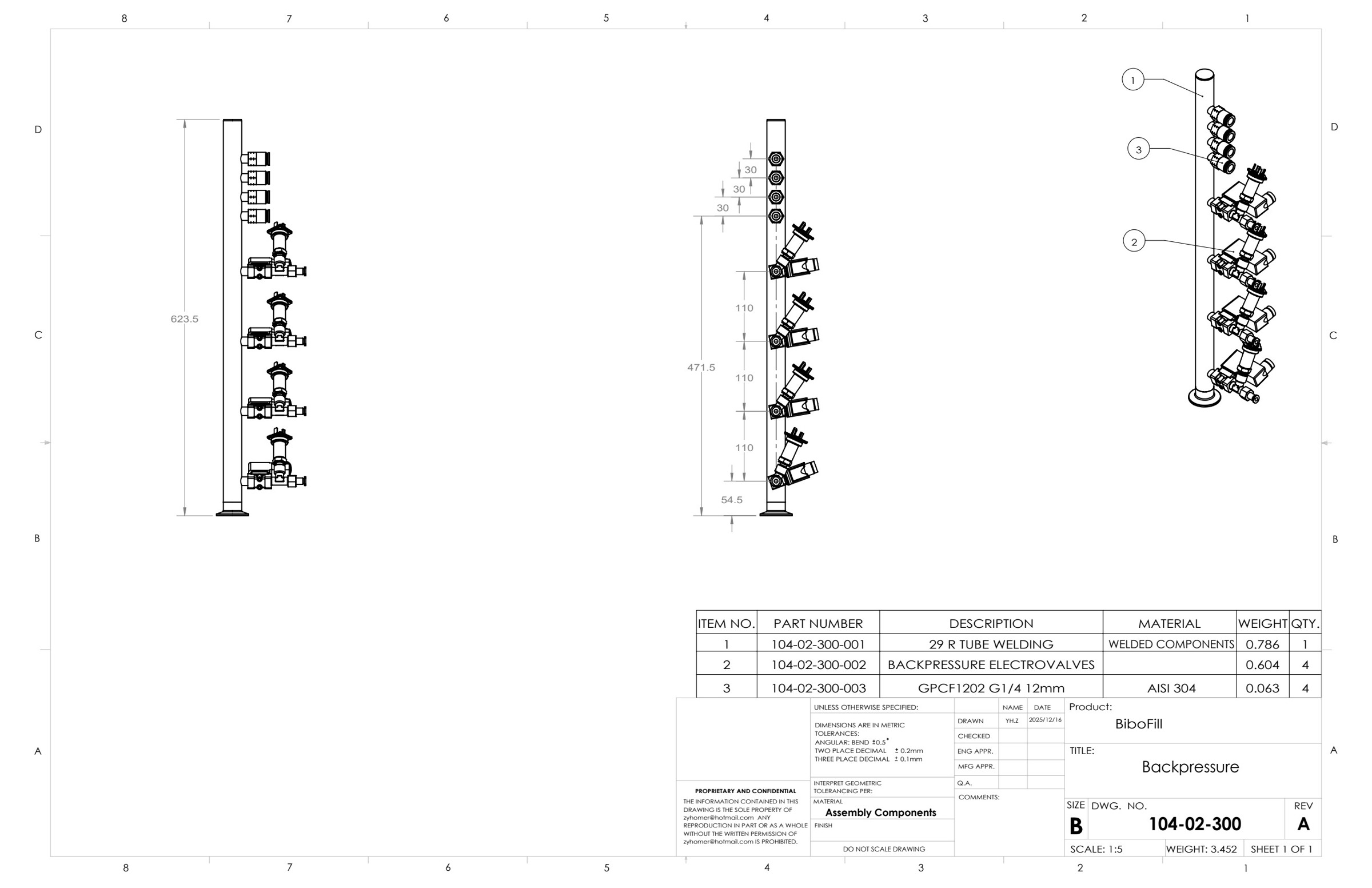
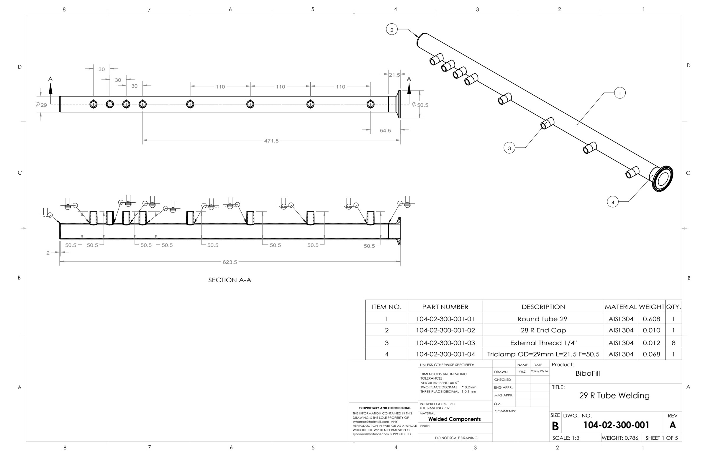
Separate drawing packages describe the beer-tube circuit and backpressure components. Tube positions, threaded connections, clamp interfaces and welded features are presented together with assembly parts lists, so the circuit can be understood at both module and component level.
- Liquid-circuit assembly with round and square tube members
- Backpressure assembly with fittings, sensors and connection interfaces
- Tube weldment drawings with port locations, sections and constituent parts
Select any image to view the full-size drawing or photograph.
HMI Enclosure & Formed Sheet-Metal Parts
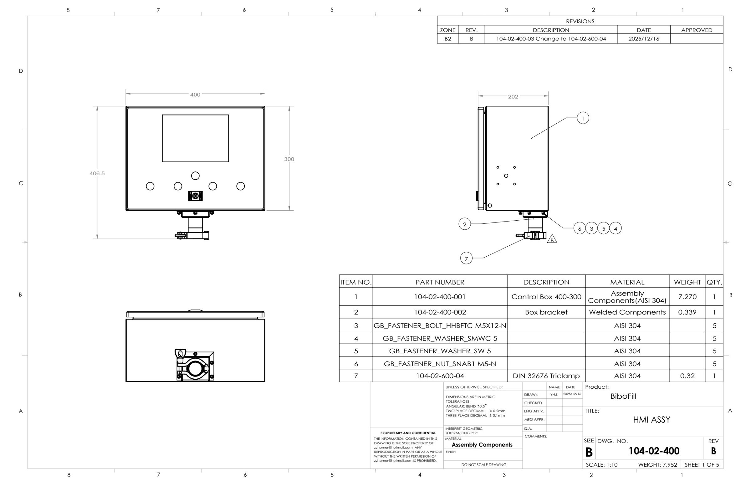
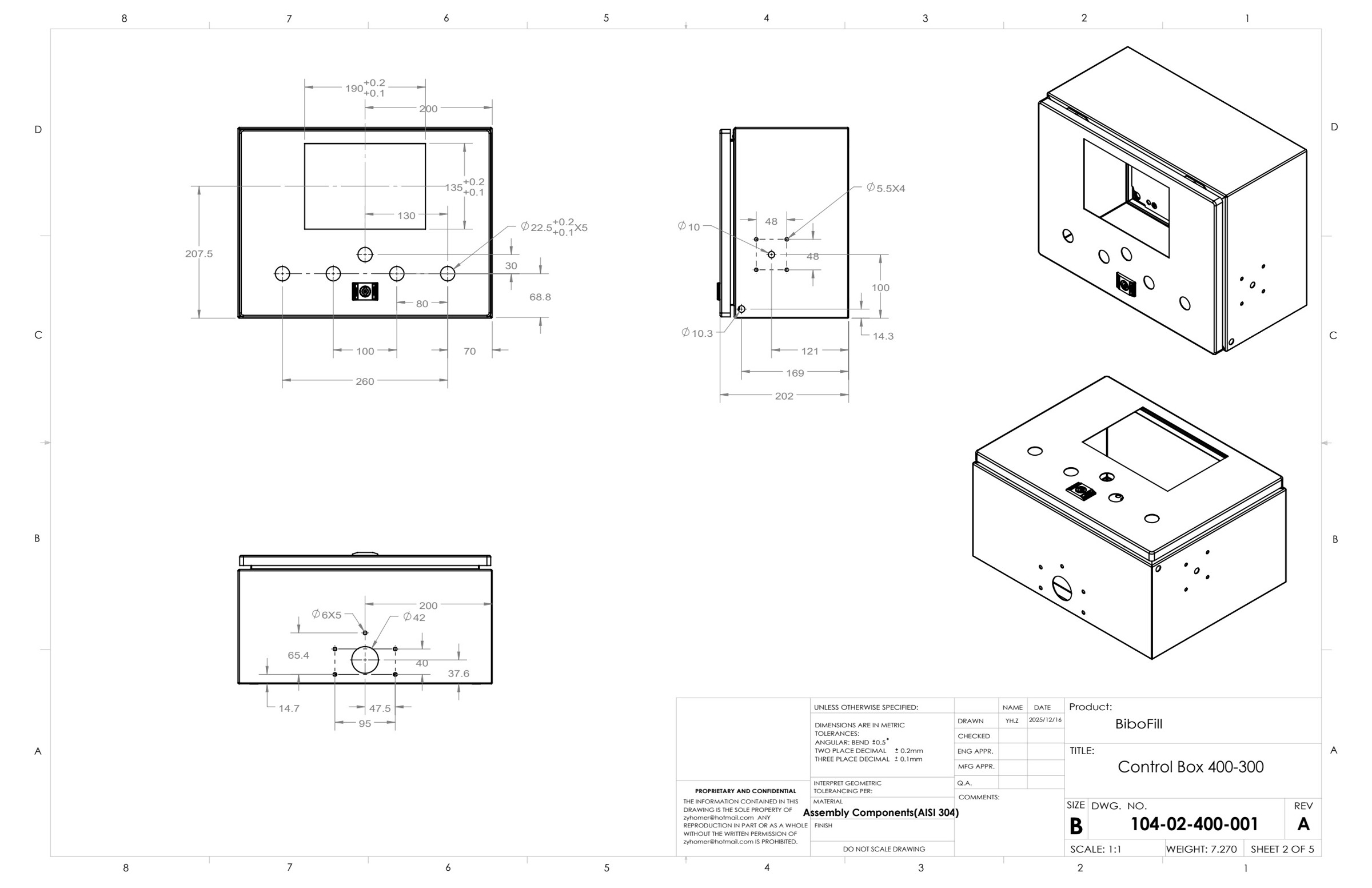
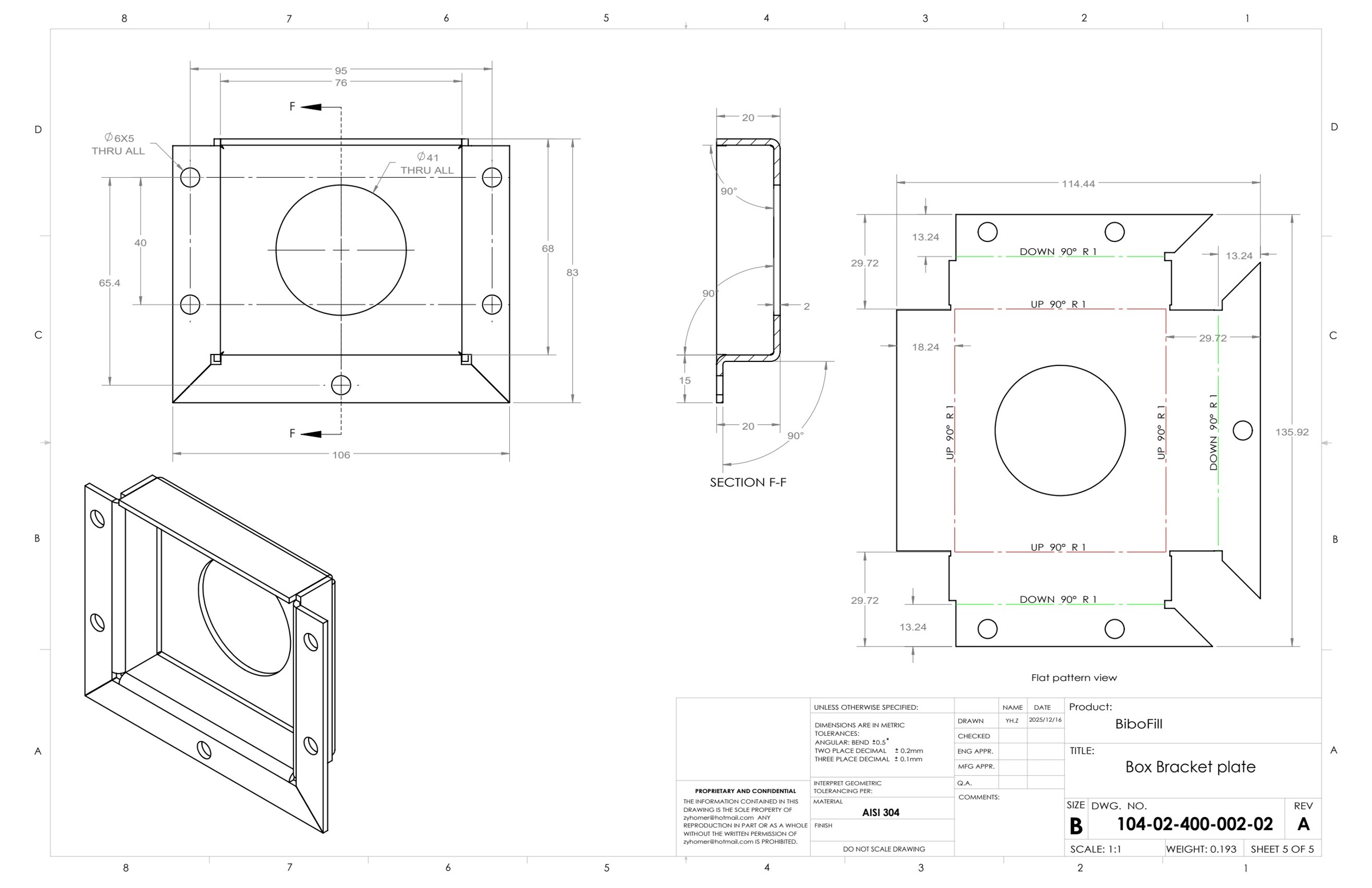
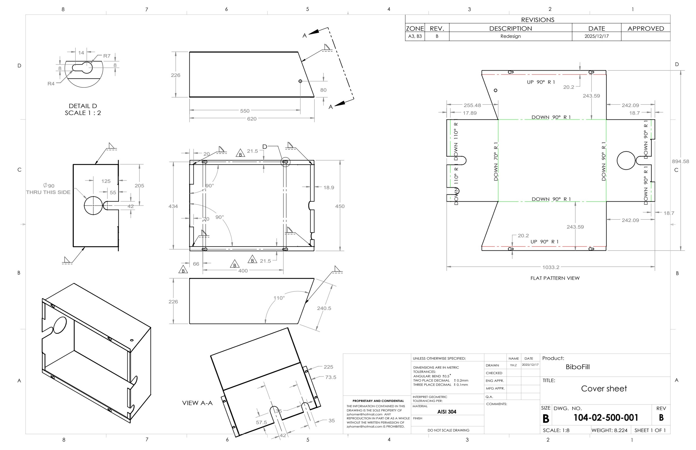
The HMI assembly combines a control enclosure, mounting bracket and clamp connection. The drawing set continues down to the enclosure openings, formed bracket and cover, pairing assembled views with flat-pattern and bend information.
- Control-box assembly, mounting interface and fastener list
- Enclosure cutouts, hole positions and multiple fabrication views
- Bracket and cover drawings with formed geometry, flat patterns and bend directions
Select any image to view the full-size drawing or photograph.
Laser-Cutting Files & Supplier Handoff
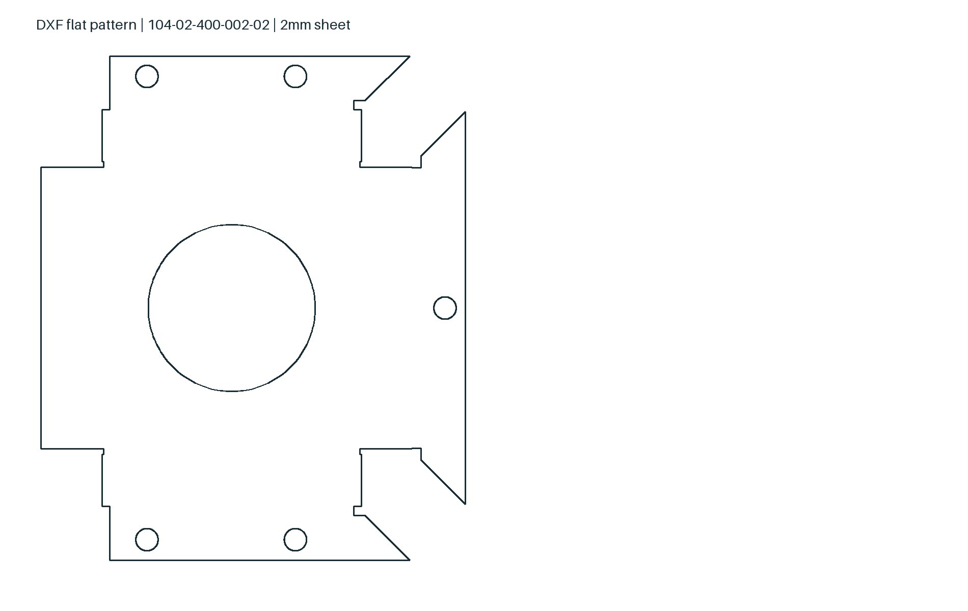
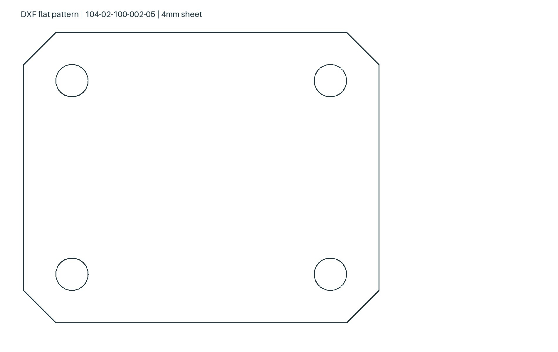
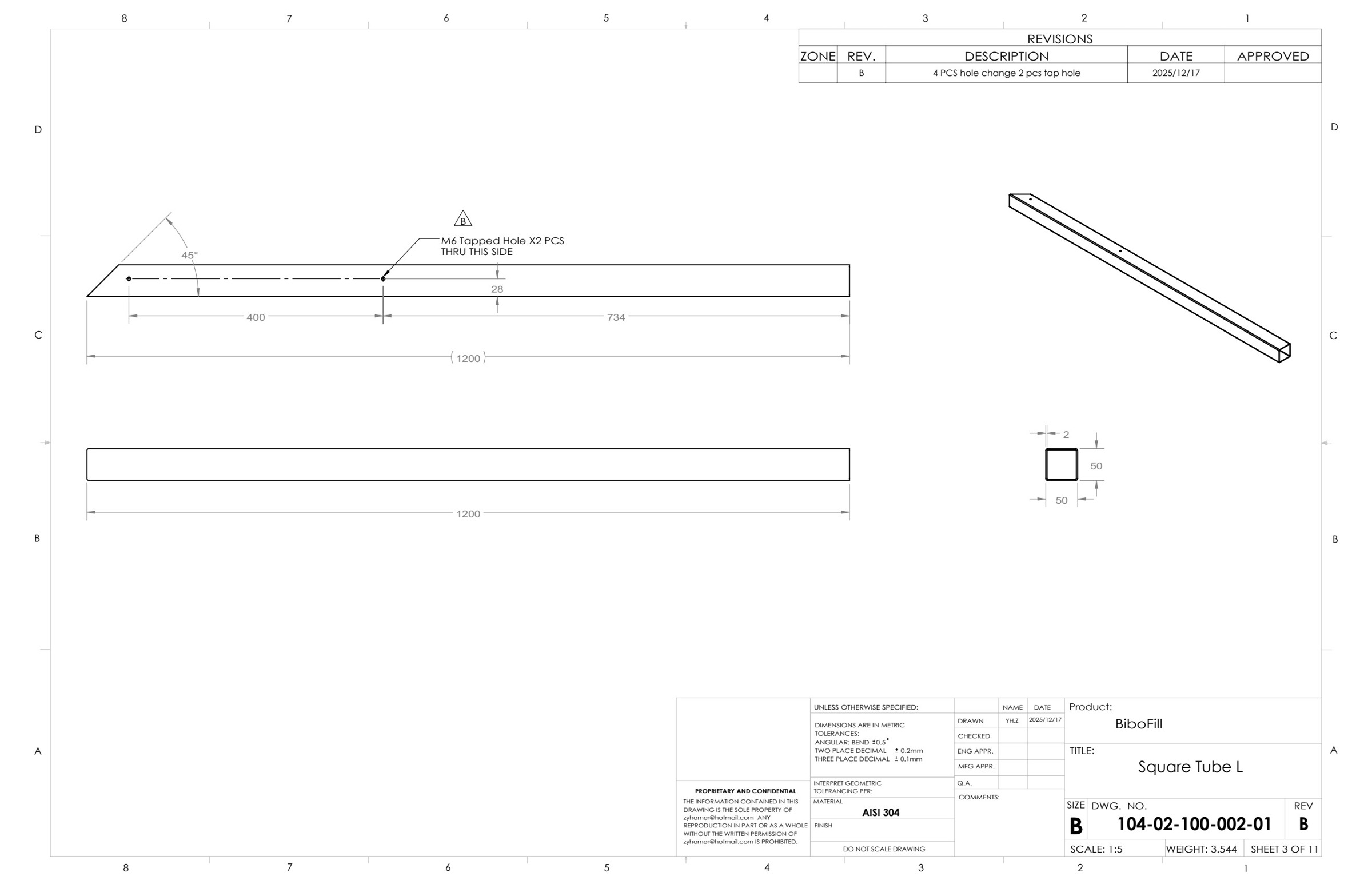
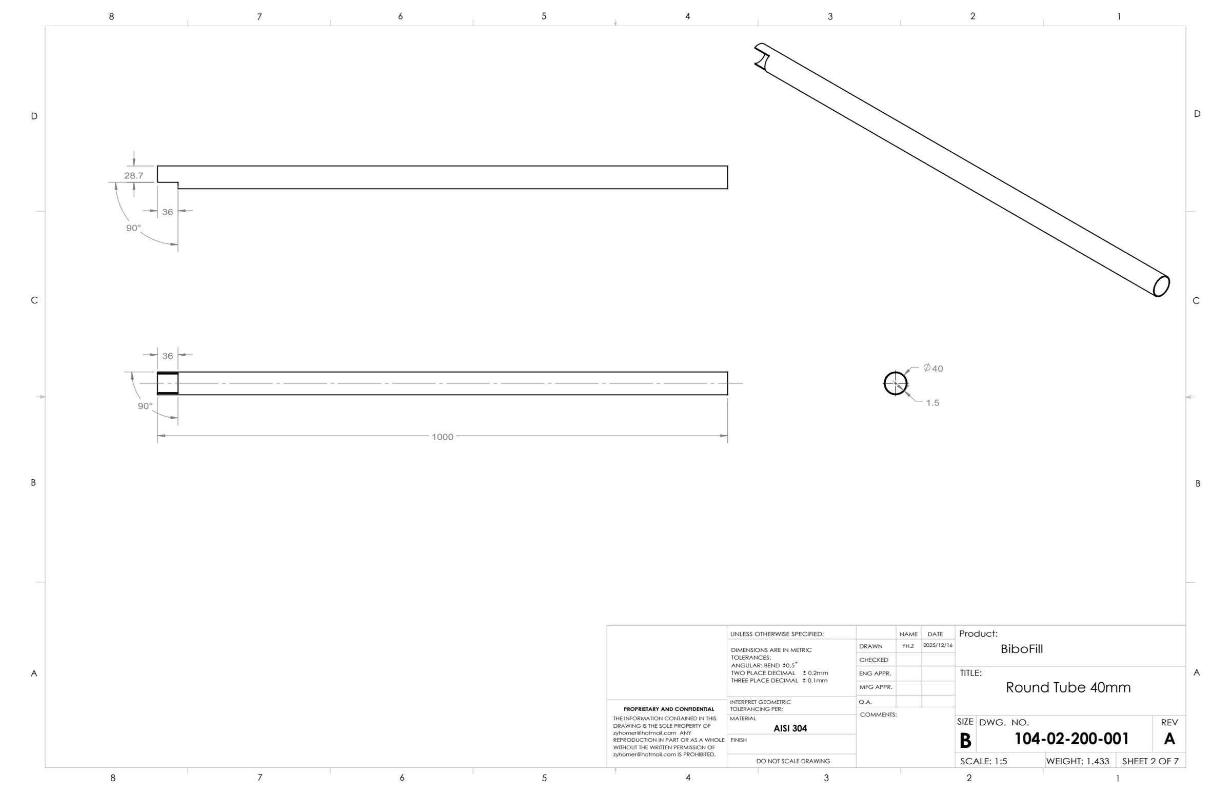
Manufacturing deliverables extend beyond PDF drawings. Sheet-metal DXFs are grouped by 1.5 mm, 2 mm and 4 mm thickness. Tube laser-cutting handoff uses STEP geometry with dimensioned tube drawings to communicate section size, wall thickness, end cuts and openings. The archive also contains Rev C full-assembly and production-only STEP exports for geometry exchange.
- 18 sheet-metal DXFs organised into thickness-based folders
- 2D cutting contours paired with forming and fabrication drawings
- Square and round tube detail covering holes, lengths, end geometry and section sizes
- Full-assembly and production-only STEP exports alongside native SolidWorks files
Select any image to view the full-size drawing or photograph.
BOM, Purchased Parts & Revision-Controlled Documentation
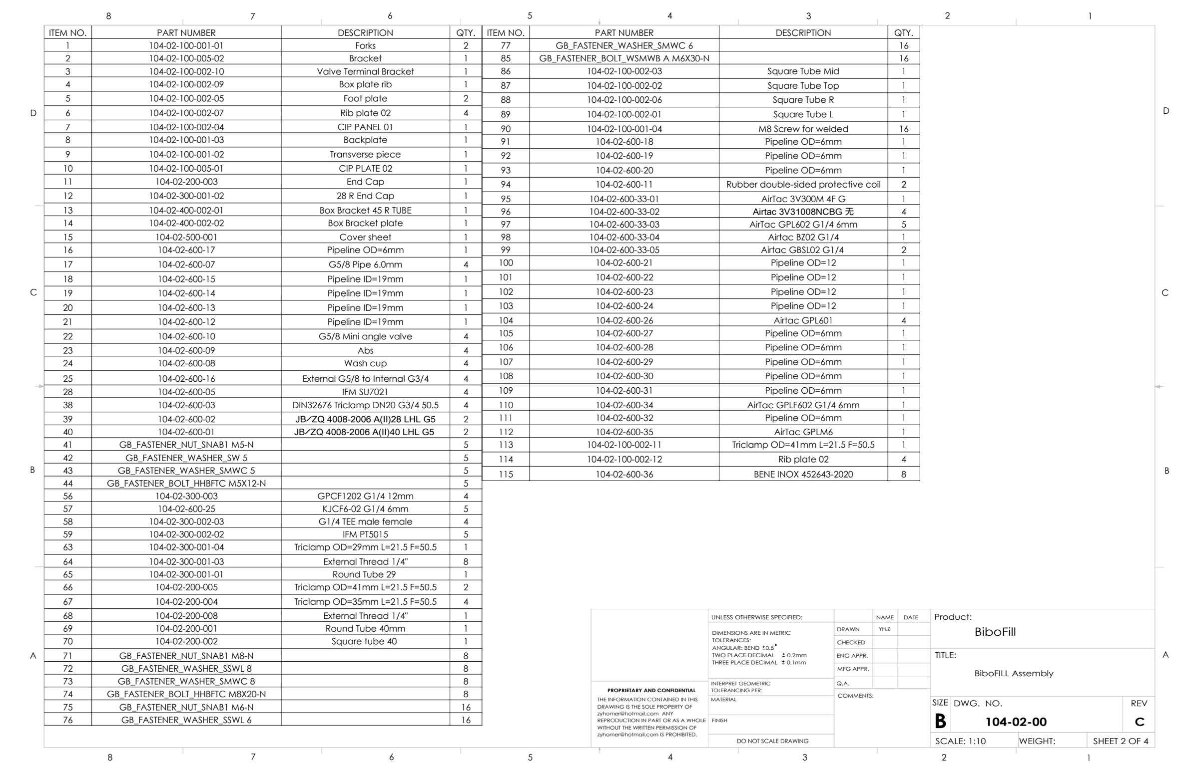
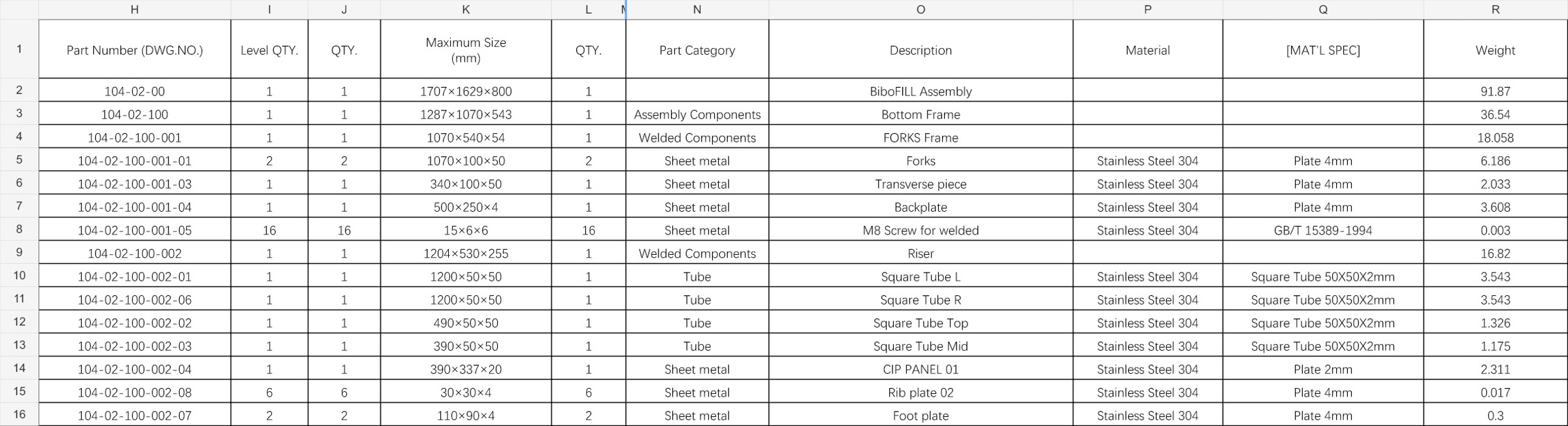
The documentation includes both assembly drawing parts lists and an Excel BOM organised by assembly level. Part numbers, descriptions, quantities, manufacturing categories, material specifications and sizes help separate fabricated parts from purchased components. The Excel example below is the 14 December 2025 snapshot; the Rev C drawing examples include later 16–17 December updates and retain their original sheet-level revisions.
- Hierarchical BOM connecting the whole machine, subassemblies and individual parts
- Separate sheet-metal, tube, welded and purchased-component categories
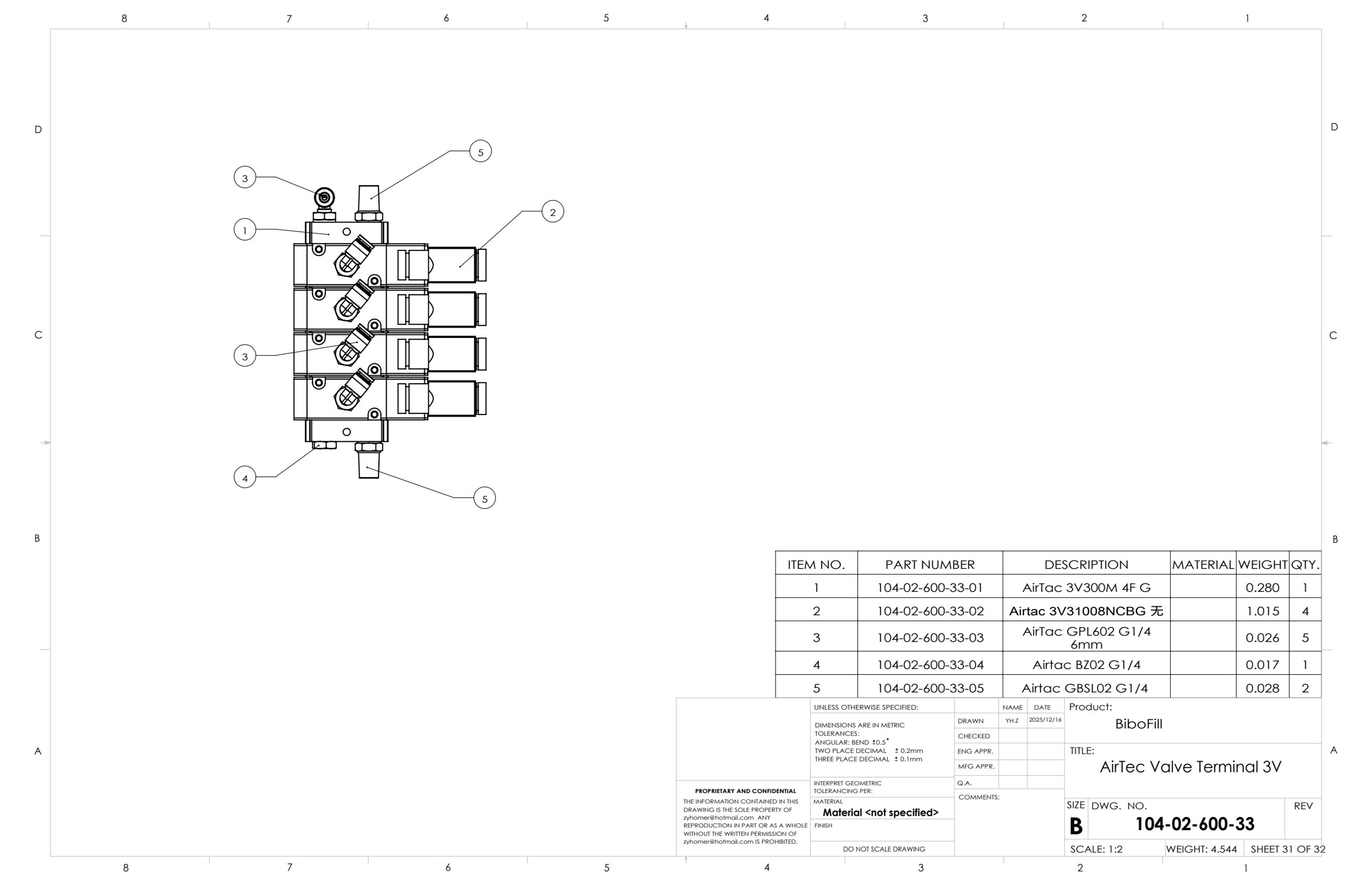
- Assembly balloons and parts lists supporting component identification
- Native CAD, PDF, DXF, STEP and Excel files serving different manufacturing tasks
Select any image to view the full-size drawing or photograph.